Drawing Checklist (Boundy 8th edition) PDF

| Title | Drawing Checklist (Boundy 8th edition) |
|---|---|
| Course | Design for Manufacture |
| Institution | University of New South Wales |
| Pages | 1 |
| File Size | 91.4 KB |
| File Type | |
| Total Downloads | 29 |
| Total Views | 142 |
Summary
Engineering Drawings Checklist...
Description
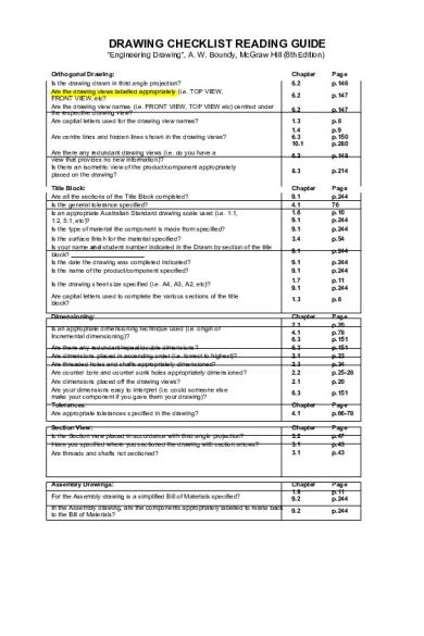
DRAWING CHECKLIST READING GUIDE “Engineering Drawing”, A. W. Boundy, McGraw Hill (8th Edition) Orthogonal Drawing: Is the drawing drawn in third angle projection? Are the drawing views labelled appropriately (i.e. TOP VIEW, FRONT VIEW, etc? Are the drawing view names (i.e. FRONT VIEW, TOP VIEW etc) centred under the respective drawing view? Are capital letters used for the drawing view names?
Chapter 6.2
Page p.146
6.2
p.147
6.2
p.147
1.3 1.4 6.3 10.1
p.8 p.9 p.150 p.280
6.2
p.148
8.3
p.214
Title Block: Are all the sections of the Title Block completed? Is the general tolerance specified? Is an appropriate Australian Standard drawing scale used (i.e. 1:1, 1:2, 5:1, etc)? Is the type of material the component is made from specified?
Chapter 9.1 4.1 1.6 9.1 9.1
Page p.244 76 p.10 p.244 p.244
Is the surface finish for the material specified? Is your name and student number indicated in the Drawn by section of the title block? Is the date the drawing was completed indicated? Is the name of the product/component specified?
3.4
p.54
9.1
p.244
9.1 9.1
p.244 p.244
Is the drawing sheet size specified (i.e. A4, A3, A2, etc)?
1.7 9.1
p.11 p.244
Are capital letters used to complete the various sections of the title block?
1.3
p.8
Dimensioning:
Chapter 2.1 4.1 6.3 6.3 2.1 2.3 2.2 2.1
Page p.20 p.78 p.151 p.151 p.23 p.34 p.25-28 p.20
6.3
p.151
Chapter 4.1
Page p.66-78
Section View: Is the Section view placed in accordance with third angle projection? Have you specified where you sectioned the drawing with section arrows? Are threads and shafts not sectioned?
Chapter 3.2 3.1 3.1
Page p.47 p.43 p.43
Assembly Drawings:
Chapter 1.8 9.2
Page p.11 p.244
9.2
p.244
Are centre lines and hidden lines shown in the drawing views? Are there any redundant drawing views (i.e. do you have a view that provides no new information)? Is there an isometric view of the product/component appropriately placed on the drawing?
Is an appropriate dimensioning technique used (i.e. origin or Incremental dimensioning)? Are there any redundant/repeat/double dimensions? Are dimensions placed in ascending order (i.e. lowest to highest)? Are threaded holes and shafts appropriately dimensioned? Are counter bore and counter sunk holes appropriately dimensioned? Are dimensions placed off the drawing views? Are your dimensions easy to interpret (i.e. could someone else make your component if you gave them your drawing)? Tolerances: Are appropriate tolerances specified in the drawing?
For the Assembly drawing is a simplified Bill of Materials specified? In the Assembly drawing, are the components appropriately labelled to relate back to the Bill of Materials?...
Similar Free PDFs

Chemistry 8th Edition Zumdahl
- 7 Pages

CCT2 8th edition hayt solutions
- 406 Pages

Textbook chapter 5 8th edition
- 72 Pages

Mechanics of Materials 8th Edition
- 1,123 Pages

CCT1 8th edition hayt solutions
- 615 Pages

Case in Point 8th Edition
- 294 Pages

Drawing Tips
- 10 Pages

Checklist
- 6 Pages

Checklist
- 8 Pages
Popular Institutions
- Tinajero National High School - Annex
- Politeknik Caltex Riau
- Yokohama City University
- SGT University
- University of Al-Qadisiyah
- Divine Word College of Vigan
- Techniek College Rotterdam
- Universidade de Santiago
- Universiti Teknologi MARA Cawangan Johor Kampus Pasir Gudang
- Poltekkes Kemenkes Yogyakarta
- Baguio City National High School
- Colegio san marcos
- preparatoria uno
- Centro de Bachillerato Tecnológico Industrial y de Servicios No. 107
- Dalian Maritime University
- Quang Trung Secondary School
- Colegio Tecnológico en Informática
- Corporación Regional de Educación Superior
- Grupo CEDVA
- Dar Al Uloom University
- Centro de Estudios Preuniversitarios de la Universidad Nacional de Ingeniería
- 上智大学
- Aakash International School, Nuna Majara
- San Felipe Neri Catholic School
- Kang Chiao International School - New Taipei City
- Misamis Occidental National High School
- Institución Educativa Escuela Normal Juan Ladrilleros
- Kolehiyo ng Pantukan
- Batanes State College
- Instituto Continental
- Sekolah Menengah Kejuruan Kesehatan Kaltara (Tarakan)
- Colegio de La Inmaculada Concepcion - Cebu


