Lab 2 bjt PDF

| Title | Lab 2 bjt |
|---|---|
| Author | Mus El |
| Course | ELECTRONIC & ELECTRICAL PRINCIPLES |
| Institution | University of Sunderland |
| Pages | 2 |
| File Size | 74.8 KB |
| File Type | |
| Total Downloads | 36 |
| Total Views | 117 |
Summary
BJT biasing circuit and calculated their operating points...
Description
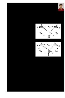
Discussion: In this experiment, we studied a couple of BJT biasing circuit and calculated their operating points. First of all, we measured the transistor’s β value, and we implemented a circuit to obtain IB/IC values. By changing the bias current (IB), we saw that the collector current (IC) changed with almost β times. We noted these IC and IB readings and calculated their β values by IC / IB. Then we plotted the transistor’s gain curve by drawing β vs. IC. The unique characteristics of the BJT originate from an interaction between these two junctions between: an emitter, a Base and a collector. The graph shows how the current varies when the voltage is increasing. the value of current is proportional to the voltage. For BJT Q2N3904, in this chart, you can see the cutoff region of operation in the area of the chart with a steep slope. After this region is the nearly horizontal region of active mode operation. Ideally, the behavior of the chart in this region would be perfectly horizontal, but since we are working with real components, nothing can be perfect.
One of the Task of the transistor is to provide DC current gain. The measurement shows exactly that. In the circuit input current Ib and output current is Ic and DC current gain can be found using Ic/Ib and its shown in the lab for voltage 2 and voltage 4v. Also the incremental resistance is found by dividing change in voltage by change in current. I think current gain does not depend on the Ib, because if Ib increase then Ic increases with similar ratio. As tested in lab, as voltage increases current gain increases as well. Resistance value is medium and that is 568 ohms. Since BJT are useful in discrete circuit design, we analyzed the static characteristic of BJT. We measured and plotted the I-V curve for collector current and collector-emitter voltage, while keeping base-emitter voltage constant.
To sum up, by using BJTs, we learned the biasing circuits and examined how their operating points can be calculated.
Conclusions As a conclusion, by using Ohm’s Law we can measured and determine the value of current, voltage and resistor on diode. The forward-bias and the reverse-bias properties of the p-n junction imply that it can be used as a diode. A p-n junction diode allows electric charges to flow in one direction, but not in the opposite direction; negative charges (electrons) can easily flow through the junction from n to p but not from p to n and the reverse is true for holes. For Bipolar Junction Transistor ( BJT )From this experiment, we are able to determine operational range of bipolar junction transistor (BJT).
REFERENCES:
1/ Semiconductors and Electronic Devices, 2nd Ed. (PrenticeHall, Englewood Cliffs, NJ, 1984) 2/ J. David Irwin, Basic Engineering Circuit Analysis, (7th Edition), John Wiley andSons Inc,2002 3/ Thomas L. Floyd, Principles Of Electric Circuits: Electron Flow Version, (3rd Edition), Macmillan Publishing Company, New York, 1993...
Similar Free PDFs

Lab 2 bjt
- 2 Pages

BJT 2021 - Lecture notes 2
- 11 Pages

BJT Fundamentals
- 22 Pages

Summary - Bjt formula
- 1 Pages

Curvas Características DEL BJT
- 7 Pages

Bias Junction Transistor (BJT
- 1 Pages

Transistor BJT - VIDEO CAPTIONS
- 11 Pages

Summary - Bjt device equations
- 19 Pages

Problems BJT dc analysis
- 2 Pages

Lab 2 - lab 2
- 5 Pages

LAB 2 - LAB 2
- 15 Pages

Amplificadores BJT y JFET
- 5 Pages
Popular Institutions
- Tinajero National High School - Annex
- Politeknik Caltex Riau
- Yokohama City University
- SGT University
- University of Al-Qadisiyah
- Divine Word College of Vigan
- Techniek College Rotterdam
- Universidade de Santiago
- Universiti Teknologi MARA Cawangan Johor Kampus Pasir Gudang
- Poltekkes Kemenkes Yogyakarta
- Baguio City National High School
- Colegio san marcos
- preparatoria uno
- Centro de Bachillerato Tecnológico Industrial y de Servicios No. 107
- Dalian Maritime University
- Quang Trung Secondary School
- Colegio Tecnológico en Informática
- Corporación Regional de Educación Superior
- Grupo CEDVA
- Dar Al Uloom University
- Centro de Estudios Preuniversitarios de la Universidad Nacional de Ingeniería
- 上智大学
- Aakash International School, Nuna Majara
- San Felipe Neri Catholic School
- Kang Chiao International School - New Taipei City
- Misamis Occidental National High School
- Institución Educativa Escuela Normal Juan Ladrilleros
- Kolehiyo ng Pantukan
- Batanes State College
- Instituto Continental
- Sekolah Menengah Kejuruan Kesehatan Kaltara (Tarakan)
- Colegio de La Inmaculada Concepcion - Cebu


