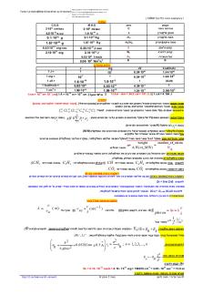
Well Control Euqations Drilling Formulas PDF

| Title | Well Control Euqations Drilling Formulas |
|---|---|
| Author | Mohamed Makhlouf |
| Course | Total Body Conditioning |
| Institution | University of Northern Iowa |
| Pages | 8 |
| File Size | 496.3 KB |
| File Type | |
| Total Downloads | 102 |
| Total Views | 162 |
Summary
well control equations ...
Description
Well Control Equations Pressure (P) – psi Pressure (psi) = Force (lb) / Area in Square Inch (in 2)
Pressure Gradient (G) – psi/ft Mud Gradient (Psi/ft ) = Mud weight ( PPG) x 0.052
Hydrostatic Pressure (HP) – psi Hydrostatic Pressure (HP) = Mud weight (PPG) x 0.052 x TVD (ft)
Bottom Hole Pressure (BHP) – psi Under static condition Bottom Hole Pressure (BHP) = Hydrostatic Pressure (HP) + Surface Pressure (SP)
Under dynamic condition Bottom Hole Pressure (BHP) = Hydrostatic Pressure (HP) + Surface Pressure (SP) + Frictional Pressure (FrP)
1|P a g e
Note: Frictional pressure acts opposite way of flow direction.
Formation Pressure (FP) – psi Formation Pressure (FP) = Hydrostatic Pressure (HP) + Shut-In Drill Pipe Pressure (SIDPP)
Equivalent Circulating Density (ECD) , ppg Equivalent Circulating Density (ECD) ,ppg = (annular pressure loss, psi) ÷ 0.052 ÷ true vertical depth (TVD), ft + (current mud weight, ppg)
Leak-off Test Equivalent Mud Weight (LOT), ppg Leak off test (ppg) = (Leak off test pressure in psi) ÷ 0.052 ÷ (Casing Shoe TVD in ft) + (Mud Weight used for LOT in ppg)
Maximum Initial Shut-In Casing Pressure (MISICP), psi This calculation is based on shoe fracture which is equal to Leak Off Test Pressure. MISICP (psi) = [LOT (ppg) – Current Mud Weight (ppg)] x 0.052 x Shoe TVD (ft)
Kill Mud Weight to Balance Formation (KMW), ppg KWM (ppg) = [Shut In Drill Pipe Pressure (SIDP), psi ÷ (0.052x True Vertical Depth (TVD) of the well, ft)] + Original Mud Weight (ppg)
2|P a g e
Slow Circulation Rate (SCR), psi SCR (psi) = Initial Circulating Pressure (psi) – Shut In Drill Pipe Pressure (psi)
Annulus Capacity Factor (ACF),bbl/ft
Final Circulating Pressure (FCP), psi
Surface To Bit Strokes, strokes
Circulating Time, minutes
Capacity Factor (CF), bbl/ft
3|P a g e
Opened End Pipe Displacement, bbl/ft
Closed end pipe displacement, bbl/ft
Height of Influx, ft
Approximate gas migration rate, ft/hr
Sacks of Barite Required For Weight-up, sx
Volume Gain From Slug, bbl
4|P a g e
Triplex Pump Output (volume), bbl/stroke
Pump Output, bbl/min
New Pump Pressure With New Pump Strokes, psi
Boyle’s Law – Gas Pressure and Volume Relationship
Mud Increment for Volumetric Method (MI), bbl
Lube Increment for Lubricate and Bleed Method (LI), bbl
5|P a g e
Bottle Capacity Required, gal
Volume of Usable Fluid, gal
Snubbing force for snubbing operation Snubbing Force (SF) = Force at wellhead (Fp) + Frictional Force – Buoyed weight of string (Wb) Total force to overcome pressure at wellbore is a summation of force at wellhead and frictional force minus buoyed weight of string. Force at wellhead (Fp) can be determined by one of following equations.
OR
Buoyed Weight of Open Ended Tubular (Wb),lb For this formula, you just use the buoyancy factor and multiply it with weight of pipe in the air.
6|P a g e
Buoyed Weight of Closed Ended Tubular without fluid in the pipe (Wb),lb This formula below is different from the 1st formula because it is used for the closed ended pipe. Weight in the air will be subtracted with buoyancy weight of pipe ran in hole. Note: 24.5 is conversion factor to make the unit in gallon.
Buoyed Weight of Closed Ended Tubular after filling the pipe (Wb),lb -> in this case, there is different fluid weight in pipe and annular
The Balance Point for closed ended and unfilled pipe is the point where the weight of pipe in the fluid equates to force created by wellhead pressure.
Note:
OR
7|P a g e
This is the second case for balance point calculation. The Balance Point for closed ended pipe and the pipe is filled with fluid.
Maximum Down Force on Jacks
Effective Area of Snubbing Jacks, square inch
Hydraulic Pressure to Snub, psi
8|P age...
Similar Free PDFs

WELL Control
- 6 Pages

Casing Drilling
- 23 Pages

Drilling Cementing
- 48 Pages

04 casing drilling
- 20 Pages

Drilling assignment 1
- 11 Pages

DIRECTIONAL DRILLING TRAINING MANUAL.PDF
- 314 Pages

Tumws 20VDA-Formulas - Formulas
- 5 Pages

Formulas
- 2 Pages

Drilling Fluids Manual
- 444 Pages

125001-Formulas - formulas sheet
- 8 Pages

DRILLING SCHOOL SECCION 3
- 36 Pages

Formulas
- 6 Pages
Popular Institutions
- Tinajero National High School - Annex
- Politeknik Caltex Riau
- Yokohama City University
- SGT University
- University of Al-Qadisiyah
- Divine Word College of Vigan
- Techniek College Rotterdam
- Universidade de Santiago
- Universiti Teknologi MARA Cawangan Johor Kampus Pasir Gudang
- Poltekkes Kemenkes Yogyakarta
- Baguio City National High School
- Colegio san marcos
- preparatoria uno
- Centro de Bachillerato Tecnológico Industrial y de Servicios No. 107
- Dalian Maritime University
- Quang Trung Secondary School
- Colegio Tecnológico en Informática
- Corporación Regional de Educación Superior
- Grupo CEDVA
- Dar Al Uloom University
- Centro de Estudios Preuniversitarios de la Universidad Nacional de Ingeniería
- 上智大学
- Aakash International School, Nuna Majara
- San Felipe Neri Catholic School
- Kang Chiao International School - New Taipei City
- Misamis Occidental National High School
- Institución Educativa Escuela Normal Juan Ladrilleros
- Kolehiyo ng Pantukan
- Batanes State College
- Instituto Continental
- Sekolah Menengah Kejuruan Kesehatan Kaltara (Tarakan)
- Colegio de La Inmaculada Concepcion - Cebu


