EEL2026 Tut-3 Overhead Line Insulators Solutions PDF

| Title | EEL2026 Tut-3 Overhead Line Insulators Solutions |
|---|---|
| Author | Savaris Kazuma |
| Course | Power Transmission & Distribution |
| Institution | Multimedia University |
| Pages | 6 |
| File Size | 281.7 KB |
| File Type | |
| Total Downloads | 38 |
| Total Views | 162 |
Summary
Solutions for questions in Tutorial 3...
Description
EEL2026 Power Transmission and Distribution
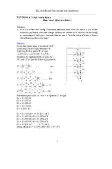
TUTORIAL # 3-Sol –some hints Overhead Line Insulators Solution 1. In a 5 insulator disc string capacitance between each unit and earth is 1/6 of the mutual capacitance. Find the voltage distribution across each insulator in the string as percentage of voltage of the conductor to earth. Find the string efficiency. How is this efficiency affected by rain? Solution Given that capacitance of insulator = mC Capacitance between pin-to-earth = C Applying KCL at point ‘P’, we get j (mC ) E 4 j (mC ) E5 j CE5
Similarly, by applying KCL at point ‘Q’, ‘R’, and ‘S’ we get the following equations: 1 E 4 1 E5 m
….
(a)
3 1 E3 1 2 E 5 ....... (b) m m 6 5 1 E2 1 2 3 E5 .............. (c) m m m 7 1 10 15 E1 1 2 3 4 E5 .... (d) m m m m 1 20 21 8 E 5 2 3 4 E5 .......(e) m m m m Substituting the value of ‚ m = 6 in equation (e) we get E4 = 1.1667 E5 E3 = 1.5278 E5 E2 = 2.1435 E5 E1 = 3.1165 E5 E = 8.9545 E5
E1 = 3.1165/8.9545 = 34.80 % of E E2 = 2.1435/8.9545 = 23.94% of E E3 = 1.5278/8.9545 = 17.06% of E E4 = 1.1667/8.9545 = 13.03% of E E5 = 1/8.9545 = 11.17% of E String efficiency = 1/(5*0.348) * 100 = 57.47%
1
EEL2026 Power Transmission and Distribution
2. Each line of a 3-phase system is suspended by a string of 3 similar insulators. If the voltage across the line unit is 17.5 kV, calculate the line to neutral voltage. Assume that the shunt capacitance between each insulator and earth is ⅛ of the capacitance of the insulator itself. Also find the string efficiency. For 3 insulator string 1 E 2 1 E3 m
….
(a)
3 1 E1 1 2 E 3 ....... (b) m m m=8 Therefore E2 = 1.125 E3 and E1 = 1.3906 E3 It is given that E1 = 17.5 kV = 1.3906 E3 E3 = 12.5843 kV E2 = 1.125*12.5843 = 14.1573 kV Line to neutral voltage E = 17.5 + 14.157 + 12.584 = 44.24 kV
String efficiency = 44.24/(3*17.5) = 84.27 % 3. A string of identical insulators is shown in Fig. 1. Compute the percentage voltage distribution across each of the suspension insulators and the string efficiency. Assume m = 10. Fig. 1
Sol we get
2
EEL2026 Power Transmission and Distribution E = 7.2181 E5 E5 = 13.85% of E E4 = 15.25% of E E3 = 18.15% of E E2 = 22.87% of E E1 = 29.88% of E % String efficiency
100 E 100 100 66.93 % 5 29.88 n E max
4. Each of three insulators forming a string has a self-capacitance of C farads. The shunting capacitance of the connecting metal work of each insulator is 0.2 C to earth and 0.1 C to the line. Calculate the voltage across each insulator as a percentage of the line voltage to earth and also the string efficiency of the arrangement. By how much does the string efficiency increase if a guard ring is provided increasing the capacitance to the line of the metal work of the lowest insulator to 0.3 C? Also find the redistribution of the voltage. Solution E2 + 0.1(E1 + E2) = 0.2 E3 + E3 0.1 E1 + 1.1 E2 -1.2 E3 = 0
(1)
E1 + 0.1 E1 = E2 + 0.2(E2 + E3) 1.1 E1 – 1.2 E2 – 0.2 E3 = 0
(2)
E1 + E2 + E3 = E
(3)
0.2C
R
0.2C Solving E1 = 0.3869 E = 38.69 % of E E2 = 0.3030 E = 30.30 % of E E3 = 0.3100 E = 31.00 % of E
C0.1C
E2 S
E1
String efficiency = 1/(3 x 0.3896) = 86.15 % With guard ring (2) becomes 1.3 E1 – 1.2 E2 – 0.2 E3 = 0 Solving E1 = 0.3495 E = 34.95 % of E E2 = 0.3242 E = 32.42 % of E E3 = 0.3263 E = 32.63 % of E
C 0.1C
E3
(2)
3
C
0.3C
EEL2026 Power Transmission and Distribution String efficiency = 1/(3 x 0.3495) = 95.37 % 5. A string of 6 suspension insulators is to be graded to obtain uniform distribution of voltage across the string. If the pin-to-earth capacitances are all equal to C and the mutual capacitances of the top insulator is 10 C find the mutual capacitance of each unit in terms of C.
C
10C
P C
C5
E5
Q C
Solution
E6
E4
C4
R For uniform distribution of voltages E1 = E2 = E3 = E4 = E5 = E6 = V Applying KCL at node P 10C V + C V = C5 V → Applying KCL at node Q 11C V + C 2V = C4 V → Applying KCL at node R 13C V + C 3V = C3 V → Applying KCL at node S 16C V + C 4V = C2 V → Applying KCL at node T 20C V + C 5V = C1 V →
E3
C3
S E2
C5 = 11C
C2
T C4 = 13C
E1
C1
C3 = 16C C2 = 20C C1 = 25C
6. A string of 8 suspension insulators is to be fitted with a grading ring. If the pin-to-earth capacitances are equal to C find the values of line-to-pin capacitances that would give a uniform voltage distribution over the string. Solution In general for sting consists of n discs, we have derived in the class that the capacitance from the gaurd ring to the jth node from the top is given by Cj =
jC n j
For this case with n = 8
C1 = C/7 C2 = 2C/6 = C/3 C3 = 3C/5 = C4 = 4C/4 = C C5 = 5C/3 C6 = 6C/2 = 3C C7 = 7C/1 = 7C 4
EEL2026 Power Transmission and Distribution 7. The potential distribution across a string of identical insulators is shown in Fig. 2. The voltage between line conductor and earth is 33 kV. Determine the percentage increase in voltage across each insulator if one of the insulators is short circuited. P
Solution Capacitance of insulator = mC Capacitance between pin-to-earth = C Writing KCL at the point ‘Q’, we get
C
j (mC ) E3 j (mC ) E4 j CE 4
C
10C
E4
Q 10C
E3
1 E 3 1 E4 m
R C
Since m = 10, we have E3 1.1E 4 Applying KCL at point ‘R’, we get 3 1 E 2 1 2 E 3 m m
10C
E2
S 10C
E1
E2 1.31E4
Similarly, by applying KCL at point ‘S’ we get 6 5 1 E 1 1 2 3 E 4 m m m E1 1.651E4 E 1.651E4 1.31E4 1.1 E4 E4 5.061 E4
As E = 33 kV, we get E4 = 6.52 kV E3 = 7.17 kV E2 = 8.54 kV E1 = 10.77 kV
C
P 10C
E4
Q
C
C
10C
E3
R 10C
E2
S 10C
E1 E When there is a short-circuit across the insulator as shown the equation at ‘Q’ vanishes. Let the voltage across the insulators be E3’, E2’, and E1’. Then E’2 = 1.1 E’3 E’1 = 1.31 E’3 5
EEL2026 Power Transmission and Distribution
E 1.31E' 3 1.1E ' 3 E ' 3 3.41 E ' 3 = 33 kV
E’3 = 9.67 kV ; E’2 = 10.65 kV; E’1 = 12.67 kV
The increase in voltage at each insulator is given by:
E ' 3 9.67 1.35 7.17 E3
(35% increase in voltage at insulator QR)
E ' 2 10.65 1.25 8.54 E2
(25% increase in voltage at insulator RS)
E '1 12.67 1.18 E1 10.77
(18% increase in voltage at insulator SE)
6...
Similar Free PDFs

Cucon 1 TUT3 Reward
- 1 Pages

TW 3 - Tut3
- 3 Pages

Tut3-2 - 3.2
- 4 Pages

Ceramic vs. Polymer Insulators
- 22 Pages

Overhead Analysis
- 6 Pages

Factory Overhead Cost Variance
- 2 Pages
![Biaya Overhead Pabrik [BOP]](https://pdfedu.com/img/crop/172x258/zdg64ml1pw74.jpg)
Biaya Overhead Pabrik [BOP]
- 17 Pages

FOH - factory overhead
- 9 Pages

Overhead Crane Design
- 50 Pages

SAP - Overhead Cost Orders
- 199 Pages

line balancing
- 22 Pages
Popular Institutions
- Tinajero National High School - Annex
- Politeknik Caltex Riau
- Yokohama City University
- SGT University
- University of Al-Qadisiyah
- Divine Word College of Vigan
- Techniek College Rotterdam
- Universidade de Santiago
- Universiti Teknologi MARA Cawangan Johor Kampus Pasir Gudang
- Poltekkes Kemenkes Yogyakarta
- Baguio City National High School
- Colegio san marcos
- preparatoria uno
- Centro de Bachillerato Tecnológico Industrial y de Servicios No. 107
- Dalian Maritime University
- Quang Trung Secondary School
- Colegio Tecnológico en Informática
- Corporación Regional de Educación Superior
- Grupo CEDVA
- Dar Al Uloom University
- Centro de Estudios Preuniversitarios de la Universidad Nacional de Ingeniería
- 上智大学
- Aakash International School, Nuna Majara
- San Felipe Neri Catholic School
- Kang Chiao International School - New Taipei City
- Misamis Occidental National High School
- Institución Educativa Escuela Normal Juan Ladrilleros
- Kolehiyo ng Pantukan
- Batanes State College
- Instituto Continental
- Sekolah Menengah Kejuruan Kesehatan Kaltara (Tarakan)
- Colegio de La Inmaculada Concepcion - Cebu


