Textbook Solution ch3 PDF

| Title | Textbook Solution ch3 |
|---|---|
| Author | Saleh Almadhoob |
| Course | Mechanics of materials |
| Institution | University of Bahrain |
| Pages | 3 |
| File Size | 213 KB |
| File Type | |
| Total Downloads | 31 |
| Total Views | 157 |
Summary
Solution Manual for the textbook ...
Description
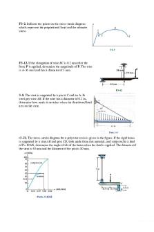
F3–2. Indicate the points on the stress-strain diagram which represent the proportional limit and the ultimate stress
F3–12. If the elongation of wire BC is 0.2 mm after the force P is applied, determine the magnitude of P. The wire is A-36 steel and has a diameter of 3 mm.
3–8. The strut is supported by a pin at C and an A-36 steel guy wire AB. If the wire has a diameter of 0.2 in., determine how much it stretches when the distributed load acts on the strut.
•3–21. The stress–strain diagram for a polyester resin is given in the figure. If the rigid beam is supported by a strut AB and post CD, both made from this material, and subjected to a load of P= 80 kN, determine the angle of tilt of the beam when the load is applied. The diameter of the strut is 40 mm and the diameter of the post is 80 mm.
F3–14. A solid circular rod that is 600 mm long and 20 mm in diameter is subjected to an axial force of P= 50 kN. The elongation of the rod is = 1.40 mm and its diameter becomes d’ = 19.9837 mm. Determine the modulus of elasticity and the modulus of rigidity of the material. Assume that the material does not yield.
3-25. The acrylic plastic rod is 200mm long and 15 mm in / diameter. If an axial load of 300 N is applied to it, determine the change in its length and the change in its diameter. E= 2.70 GPa, v = 0.4
3-27. The elastic portion of the stress-strain diagram for a steel alloy is shown in the figure. The specimen from which it was obtained had an original diameter of 13 mm and a gauge length of 50 mm. When the applied load on the specimen is 50 kN, the diameter is 12.99265 mm. Determine Poisson’s ratio for the material.
3-28. The elastic portion of the stress-strain diagram for a steel alloy is shown in the figure. The specimen from which it was obtained had an original diameter of 13 mm and a gauge length of 50 mm.. If a load of P = 20 kN is applies to the specimen, determine its diameter and gauge length. Take v = 0.4. 3–31. The shear stress–strain diagram for a steel alloy is shown in the figure. If a bolt having a diameter of 20 mm. is made of this material and used in the double lap joint, determine the modulus of elasticity E and the force P required to cause the material to yield. Take = 0.3.
•3–33. The support consists of three rigid plates, which are connected together using two symmetrically placed rubber pads. If a vertical force of 5 N is applied to plate A, determine the approximate vertical displacement of this plate due to shear strains in the rubber. Each pad has cross-sectional dimensions of 30 mm and 20 mm. Gr = 0.20 MPa.
3–42. The bar DA is rigid and is originally held in the horizontal position when the weight W is supported from C. If the weight causes B to be displaced downward 0.625mm, determine the strain in wires DE and BC. Also, if the wires are made of A-36 steel and have a cross-sectional area of 1.25mm2 , determine the weight W.
*3–44. The A-36 steel wire AB has a cross-sectional area of 10 mm2 and is unstretched when =45.00. Determine the applied load P needed to cause = 44.9°....
Similar Free PDFs

Textbook Solution ch3
- 3 Pages

Neuroscience Textbook Ch3
- 4 Pages

Solution ch3 - engel
- 14 Pages

TD solution ch3 - 교과서 솔루션
- 10 Pages

Chapter 13 - Textbook solution
- 54 Pages

CH3
- 45 Pages

Ch3 Examples
- 6 Pages

Ch3 Solutions
- 5 Pages

Ch03 - CH3
- 52 Pages

CH3 Companies
- 3 Pages
Popular Institutions
- Tinajero National High School - Annex
- Politeknik Caltex Riau
- Yokohama City University
- SGT University
- University of Al-Qadisiyah
- Divine Word College of Vigan
- Techniek College Rotterdam
- Universidade de Santiago
- Universiti Teknologi MARA Cawangan Johor Kampus Pasir Gudang
- Poltekkes Kemenkes Yogyakarta
- Baguio City National High School
- Colegio san marcos
- preparatoria uno
- Centro de Bachillerato Tecnológico Industrial y de Servicios No. 107
- Dalian Maritime University
- Quang Trung Secondary School
- Colegio Tecnológico en Informática
- Corporación Regional de Educación Superior
- Grupo CEDVA
- Dar Al Uloom University
- Centro de Estudios Preuniversitarios de la Universidad Nacional de Ingeniería
- 上智大学
- Aakash International School, Nuna Majara
- San Felipe Neri Catholic School
- Kang Chiao International School - New Taipei City
- Misamis Occidental National High School
- Institución Educativa Escuela Normal Juan Ladrilleros
- Kolehiyo ng Pantukan
- Batanes State College
- Instituto Continental
- Sekolah Menengah Kejuruan Kesehatan Kaltara (Tarakan)
- Colegio de La Inmaculada Concepcion - Cebu


