Electrical & Electronic Principles PDF

| Title | Electrical & Electronic Principles |
|---|---|
| Course | Electrical & Electronic Principles |
| Institution | De Montfort University |
| Pages | 13 |
| File Size | 663 KB |
| File Type | |
| Total Downloads | 109 |
| Total Views | 149 |
Summary
Download Electrical & Electronic Principles PDF
Description
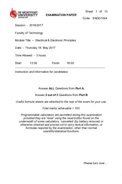
Sheet 1 of 13 EXAMINATION PAPER Code: ENGD1004 Session - 2016/2017 Faculty of Technology Module Title – Electrical & Electronic Principles Date - Thursday 18 May 2017 Time Allowed - 3 hours Start 13:00 Finish 16:00 _________________________________________________________ Instruction and information for candidates:
Answer ALL Questions from Part A Answer 2 out of 3 Questions from Part B Useful formula sheets are attached to the rear of the exam for your use. Total marks achievable = 100. Programmable calculators are permitted during this examination provided they are ‘reset’ using the reset button found on the underneath of some calculators, ‘cancelled’ (by battery removal) or otherwise checked and proved not to carry textual information, or formulae required by the examination, other than normal scientific/statistical functions.
Please turn over…
Code: ENGD1004 Sheet 2 of 13
Part A (Answer ALL Questions from Part A) A1. a)
Reduce the circuit in Fig A1.a) to a single resistor at terminals A-B. 10W
10W A
6W
4W
20W 8W
16W
B
Fig A1.a) b)
(5 marks)
Calculate the voltage across the 26W resistor and current flowing in the 24W resistor in Fig A1.b). 26W
24V
8W
Fig A1.b)
24W
(5 marks)
Please turn over…
Code: ENGD1004 Sheet 3 of 13
A2. a)
Convert the circuit shown in Fig A2.a) to Thevenin’s equivalent circuit. Draw and label the Thevenin’s equivalent circuit.
0.3A
150W
Fig A2.a) (5 marks) b)
A d.c. source has an open circuit voltage of 24V and internal resistance of 2.1W. Determine: i) The value of the load resistance that gives maximum power dissipation (1 mark) ii) The current flowing in the circuit (2 marks) iii) The value of this maximum power in i) (2 marks)
Please turn over…
Code: ENGD1004 Sheet 4 of 13
A3. a)
Name the arrangement of transistors in the circuit shown in Fig A3.a), and explain the function of the diodes. (2 marks)
TR1
TR3
A
B
TR2
TR4
Fig A3.a) Copy and complete the table below to show the logic states (On / Off) of the gates of the transistors for the given directions of the motor. Motor direction Clockwise
TR1
TR2
TR3
TR4
Anti-clockwise Stop (3 marks) b)
A 360V d.c. motor having an armature resistance of 0.8W and running at 30rev/s has an armature current of 50A. Determine: i)
The back e.m.f. (2 marks)
ii)
The torque developed (3 marks) Please turn over…
Code: ENGD1004 Sheet 5 of 13
A4. a)
A differential amplifier has an open-loop voltage gain of 100 when the input signals are 4.90V and 4.75V. Determine the output voltage of the amplifier. (3 marks)
b)
For the comparator circuit shown in Fig A4.b), the thermistor shown has a resistance of 40kΩ at 35°C. Determine: i)
The output voltage at B at a temperature of 35°C. (2 marks)
ii)
The suitable values of resistors in the 1kΩ to 10kΩ range, for the comparator circuit to switch at 35°C. (3 marks) +10V
R1
20kΩ A + B
R2
Thermistor
0V
Fig A4.b) c)
An Op-amp can be used as a band pass filter. Sketch the band pass frequency response curve to illustrate its working principle. (2 marks)
Please turn over…
Code: ENGD1004 Sheet 6 of 13
A5. a)
The following two programs were written by a careless programmer and contain errors. In the first example the programmer is trying to test if the variable 'a' is equal to zero, however the output from the program is always, 'a is not zero' even when the programmer ensures that a is zero. Explain what is wrong with this program.
(5 marks) b)
More generally, what are the smallest and largest numbers which may be represented using 'n' bits, where 'n' is an integer.
(5 marks)
Please turn over…
Code: ENGD1004 Sheet 7 of 13
A6. a) Produce a truth table for a single bit half adder and show how this may be constructed using logic gates. (5 marks) b) Show how two half adders may be combined to form a full adder. (5 marks)
Please turn over…
Code: ENGD1004 Sheet 8 of 13
Part B (Answer 2 out of 3 Questions from Part B – Do not attempt more than 2 Questions) B1. a)
Explain the term “time constant” in relation to a RC electrical circuit. (3 marks)
b)
If, in part (a), the resistor has a value of 1M Ohms and the capacitor has a value of 1.5µF, calculate the associated time constant. (2 marks)
c)
For the arrangement shown in Fig B1.c), determine: i)
The equivalent capacitance of the circuit (2 marks)
ii)
The voltage across AB (3 marks) 9µF 10µF 6µF
A
B
120V
Fig B1.c) d)
A coil of resistance 5W and inductance 120mH in series with a 100µF capacitor and a 10W resistor, is connected to a 120V, 60Hz supply. Calculate: i)
The circuit current
ii)
The circuit phase angle
(5 marks) Please turn over…
Code: ENGD1004 Sheet 9 of 13
(2 marks) iii)
The voltage across the coil (2 marks)
iv)
The voltage across the capacitor (1 mark)
B2.
a)
The circuit shown in Fig B2.a) was designed to power an iPod player from a car battery in which the voltage varies from 10V to 14.4V. The IPod player operates at 4.7V with a maximum current of 100mA.
Fig B2.a) i)
Name the component X (1 mark)
ii)
State the voltage rating that should be chosen for X (1 mark)
iii)
State the orientation of the component X in this circuit (1 mark)
It was found that component X required a minimum current of 6mA to operate, and this car battery delivered a current of 100mA to the load. iv)
v)
Calculate the total current flow through R under these conditions (1 mark) Calculate the ideal value for resistor R (when input voltage is the lowest, i.e. 10V) Please turn over…
Code: ENGD1004 Sheet 10 of 13
(2 marks) vi)
The power dissipated in the component X (1 mark)
b)
Sketch a suitable circuit to power an LED, which consists of an On-Off switch, a resistor and a 9V battery. Assuming the forward voltage across the LED is 2V, and the current through the LED should be limited to a maximum of 15mA, determine the value of the resistor. (4 marks)
c)
List two common applications of a transistor. (2 marks)
d)
For the transistor circuit shown in Fig B2.d), determine: i)
The values of IB assuming VBE =0.7. (2 marks)
ii)
The values of IC if hFE = 120. (2 marks)
iii)
The value of current IC for the transistor to be considered ‘saturated’. State whether the transistor would be saturated. (3 marks)
RL 100Ω
RB
IC
10kΩ
IB
B
C
VS 5V
E Fig B2.d)
Please turn over…
Code: ENGD1004 Sheet 11 of 13
B3. For the truth table shown in Figure B3:
Fig B3) a)
Transfer the truth table to a Karnaugh map and Identify groups on the Karnaugh map. (5 marks)
b)
Produce a minimal sum of products expression from the Karnaugh map. (5 marks)
c)
Sketch a circuit using AND/OR gates to implement this expression. (5 marks)
d)
Sketch another circuit to implement this expression using only NAND gates. (5 marks)
Please turn over…
Code: ENGD1004 Sheet 12 of 13
Useful formula
Please turn over…
Code: ENGD1004 Sheet 13 of 13...
Similar Free PDFs

Electrical & Electronic Principles
- 13 Pages

ELECTRONIC PRINCIPLES
- 1,118 Pages

Citations Electronic
- 2 Pages

Electronic Business
- 164 Pages

Electronic Conveyancing
- 4 Pages

Electronic Government
- 86 Pages
Popular Institutions
- Tinajero National High School - Annex
- Politeknik Caltex Riau
- Yokohama City University
- SGT University
- University of Al-Qadisiyah
- Divine Word College of Vigan
- Techniek College Rotterdam
- Universidade de Santiago
- Universiti Teknologi MARA Cawangan Johor Kampus Pasir Gudang
- Poltekkes Kemenkes Yogyakarta
- Baguio City National High School
- Colegio san marcos
- preparatoria uno
- Centro de Bachillerato Tecnológico Industrial y de Servicios No. 107
- Dalian Maritime University
- Quang Trung Secondary School
- Colegio Tecnológico en Informática
- Corporación Regional de Educación Superior
- Grupo CEDVA
- Dar Al Uloom University
- Centro de Estudios Preuniversitarios de la Universidad Nacional de Ingeniería
- 上智大学
- Aakash International School, Nuna Majara
- San Felipe Neri Catholic School
- Kang Chiao International School - New Taipei City
- Misamis Occidental National High School
- Institución Educativa Escuela Normal Juan Ladrilleros
- Kolehiyo ng Pantukan
- Batanes State College
- Instituto Continental
- Sekolah Menengah Kejuruan Kesehatan Kaltara (Tarakan)
- Colegio de La Inmaculada Concepcion - Cebu


![Digital Logic Design Lesson 03 - Electrical & Electronic Symbols Fundamentals [2021]](https://pdfedu.com/img/crop/172x258/xw2peoy4p0r5.jpg)


